|
|||
|
|
|||
|
| Parts List for this demonstration: |
|---|
The difference between the two examples (Basic Multi-Stop elevator, and this Floating Switch Multi-Stop elevator), are small. However, the wall with those three switches, is replaced with the Floating Switch. The Floating Switch has a bit more things to do, but are all worth it in the long run.
If any of this gets confusing, and you have NOT read the previous section Basic Multi-Stop Elevators, then Grendel suggests you go read it.
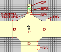 |
Following this plan here, we setup the polygons
much like the Multi-Stop elevator example. The key for this (and
all following diagrams): |
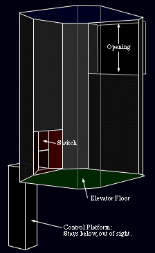 Use the same heights
for doorways and floors as before,
Those Return Switches(RS) are put in the halls outside the elevator, so that if the elevator goes up without the player, they have a way to control the elevator to bring it to their level to get back on it. An RS does not need to be put on the top most level, since the elevator will never move up past the floor of this level. Link the RS's to the SP1 Platform, via a simple platform switch.
Now, the Switch Platforms have heights of:
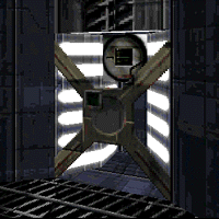 Hold off on texturing
till you have filled out all the data for the platforms. Then
after you have done that right, texture up everything as you would
like. Make sure to place a switch texture (linked to SP1) on the
face that will be a nice square, like the picture to the left
here.
Then afterwards, make the LINE that borders between the SP2 and CP; NON-Transparent, and SOLID. This will change the color of the line in Draw View (it's green in the above diagram). This is done so that when in Infinity, you will not see this CP at all when in map view.
Now that the
polygons are setup with the right floor and ceiling heights, it
is time to set all the platform attributes. Follow the following
four dialogs for each platform, and an explanation (if you need
it) is at the bottom of them all.
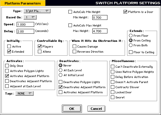
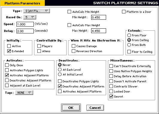
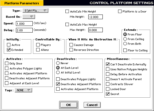
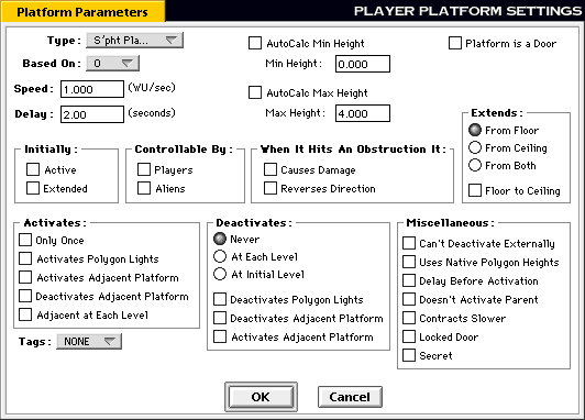
 How & Why:
SP1(MinHeight)=FloorHeight + 0.70
SP1(MaxHeight)=TopDoorwayFloorHeight + 0.70
SP2(MinHeight)=FloorHeight + 0.45
SP2(MaxHeight)=TopDoorwayFloorHeight + 0.70
The heights for the CP and P are the same as they were for
the Basic Multi-Stop example.
Activate Adjacent on Activate should be checked for
SP1 and SP2 only.
Deactivate Adjacent on Deactivate should be checked for
CP, SP1 and SP2 only.
Deactivates at Each Level is only set for the CP. All
the others are set to Never.
Make sure that only the CP cannot be Deactivated Externally.
If you set any of the others, it might not stop when you want
it to stop, and might keep going forever.
Ok, how does this work you say? Simple.
By having SP1 set to be a door, the player activates this door (thinking they are actually activating the switch visible behind the door), this SP1 then activates both SP2 and P at the exact moment. The SP2 then activates the CP also at that exact same moment. So when the player hits that SP1 door/switch everything starts up all at once. Everything continues to move till the CP reaches its "Deactivate at Each Level" (or 2wu in this example), and everything then stops. Once again when the player activates SP1, the cycle is started again, and they move to the next level, and so forth and so on, till they reach the top, which then they go downwards doing the same thing.
The switch actually turns on and does it's activate animation because it is linked to SP1, and since SP1 goes into its active mode, the switch must (by Marathon Engine parameters) go into its active state aswell, since it is a Platform Switch. All the Return Switches(RS) will also do this same thing when the elevator is in motion.
All of the above is in an example map, so if you wish to see it in action, then Download it.
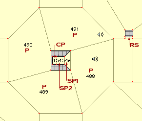
This diagram to the left shows a Floating Switch in a central
pilar on a Four-Stop elevator. This is just one of the ways you
can move and alter things to make new odd designs for these techniques.
This particular one is from "Mr.Bill meets Gumby" (a
level in Marathon:EVIL).