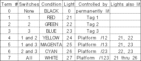
|
|||
|
| Multiple-Message Terminals |
|
Multiple-Message Terminals
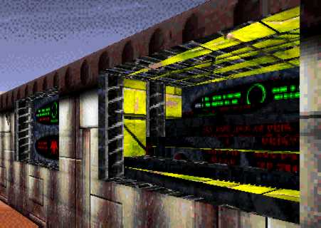
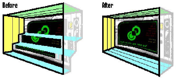
BASIC OPERATION The fundamental idea behind this technique is that if the Action key is used when facing an inactive terminal, Marathon will look further along the player's line of sight in an attempt to find an active one. The search continues until a solid wall (negative space) is reached, or the distance limit for activating a terminal is exceeded. (The search may also be halted by a completely closed platform, I haven't tested this condition.) Any number of terminals can be stacked up, and the frontmost one which is light-activated and lit (or that isn't light-activated, but that would be useless) will be accessed by the Action key. I'm pretty sure that this would work with other types of control panels as well (pattern buffers, switches, and rechargers), but that doesn't seem likely to be useful. CONSTRUCTION To make a multi-message terminal, start by building an inset in a wall, just as you would for a normal terminal. Set its floor and ceiling heights as usual, to match the terminal texture. For each additional message that is to be displayed, add an additional polygon of the same width (either rectangular or triangular) behind the inset. Use the same ceiling height, but add a little to the floor height (perhaps 0.05 WU or less) for each successive polygon to produce a stair-step effect. Each stair riser will have a terminal texture placed on it: each will have a different terminal script number and light number, and each must have the Light-Activated box checked.
Don't worry about texture alignment at this point - the backmost terminal can easily be adjusted later, and the other terminals will be completely invisible once you're done. Once the multi-terminal has been completely debugged (and don't be too quick to decide this), you can clean it up so that it looks like a normal terminal. Set all of the polygons in the terminal inset to the same floor height, and perform any needed texture alignment on the back terminal. You'll probably want to move the points on the sides closer together, so that the total depth of the inset matches that of your other terminals. If you do this, you'll also need to touch up the textures on the side walls, since they will no longer be aligned properly. Note that when you're done, the terminals other than the one in back will not have a single pixel visible from any direction, and will be completely undetectable by any means other than examining the map in an editor - but Marathon still knows they're there, and will check them in order from front to back when the Action key is used here. TERMINAL & LIGHT ASSIGNMENT The procedure above glossed over the need to create lights to control the terminals, and indeed no universal answer is possible - it all depends on exactly how and when you want your terminal messages to change. Here are some general hints, and solutions for some specific cases.
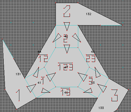
AND GATES REVISITED Missed Island discusses a couple of techniques for implementing an AND gate - in electronic terms, a circuit whose output is active only if every one of its inputs is active. Those techniques involve one creature shooting at another, with intervening platforms or liquids (controlled by the inputs) that can block the projectile, preventing it from hitting a switch (which controls the output). Described here will be a completely inorganic form of AND gate. It has a higher cost in terms of number of platforms needed, but is much easier to set up as it is completely independent of the physics model and shapes file that are used, and its response time is not affected by the player's selected difficulty level. Note that it is easy to build an OR gate - a circuit whose output is active if at least one of its inputs is active. Up to 8 input platforms can surround an output platform, and any one of the inputs can trigger the output by setting an appropriate flag. Now, here's the trick: if you invert (interchange the 'active' and 'inactive' states) all of the inputs and the output of an OR gate, the result is an AND gate. (And likewise, inverting the inputs and output of an AND gate produces an OR gate. These are known as De Morgan's Laws, in case you ever get asked on a quiz show.) To invert the state of a platform, set its Deactivate Adjacent on Activating and Activate Adjacent on Deactivating flags, and put another platform next to it - the new platform will be active when the original is inactive, and vice versa. The desired form of output for our uses here will be a light, which is even easier to invert: just set the light parameters so that it is dark when active, and bright when inactive. Remember, for purposes of a light-activated terminal (or other control panel), it is the actual brightness of the light that counts (76% or higher allows activation), not the active or inactive state of the light. Before we proceed, let me introduce another bit of digital electronics notation. The name of a condition, with a bar over it or a slash in front of it, represents the inverse of that condition. Much of the mechanism I'll be describing here works with inverted conditions (and coincidentally, the same is true of much actual electronics), so this notation saves a lot of space over writing "the inverse of" or "NOT" each time. I've used overbars in the labels on the actual map, but I'll have to use slashes here in the text since my word processor doesn't support overbars. Examples: /1 represents a platform that is active only when tag 1 is inactive, and /12 is a platform that is active when either tag 1 or tag 2 is inactive. The mechanism for the demo map needs to be able to distinguish each possible combination of its three inputs, which are switches controlling tags number 1 (left), 2 (middle), and 3 (right). The specific outputs needed are each combination of two active inputs (1 AND 2, 1 AND 3, 2 AND 3), and for all three inputs being active (1 AND 2 AND 3). These are implemented using De Morgan's Law as mentioned above: for example, 1 AND 2 is actually built as NOT(/1 OR /2). To save platforms, each of the three tags is inverted once, and the result is shared between the OR gates using that input. This has the effect of turning the whole mechanism into a single, indivisible lump, rather than four independent gates.
The inverted platforms also have Deactivate Never set. They move fast, have a short range of motion, and have the Activate Adjacent At Each Level flag set, so they constantly activate the nearby platforms (except for the input platform that triggered them, due to use of the Don't Activate Parent flag). The output platforms (/12, /13, /23, and /123) are also fast moving, and have Deactivate At Each Level set so that they will quickly shut off in the absence of signals from /1, /2, or /3. The output platforms control no further platforms (which would be disastrous, they're adjacent to too many other things), but instead control lights (24 thru 27) which are used to activate terminals, and also form part of the diagram on the floor. As mentioned earlier, these outputs need to be inverted, which is done by assigning 0% brightness to the active state of the lights, and 100% brightness to their inactive state. The lights also have to handle the fact that the platforms controlling them are not quite continuous: there are regular brief pauses between the time that the output platforms deactivate themselves and the next time an input platform reactivates them. This is accomplished by assigning a Becoming Inactive phase that extends the Active phase's brightness (0%) for 10 ticks, long enough to cover up these pauses. STARTUP CONSIDERATIONS The mechanism as described so far performs just fine once it's running, however it has a problem at startup time. Consider what the initial state of the platforms ought to be:
The problem is that platform /1 will also activate platform 1, getting the mechanism out of sync with the tag switches. The Can't Activate Parent flag on /1 doesn't prevent this, since an initially active platform doesn't have a parent. It is therefore necessary to start up the mechanism in the opposite state: 1 active, /1 inactive. An additional platform labeled INIT (not visible in the diagram above) starts out active, but quickly deactivates itself and the adjacent platforms 1, 2, and 3, placing the mechanism in the desired initial state. INIT has the Activates Only Once flag set, and therefore has no further effect on anything. The need to have the INIT platform adjacent to all three inputs resulted in the rather strange shape of those platforms. USING THE OUTPUTS Note that the mechanism does not supply a single, distinct output for each of the eight possible combinations of its inputs. In particular:
As mentioned before, it is not necessary to activate exactly one terminal at a time: it is sufficient to recognize the conditions where more than one terminal is active, and make sure that the proper one is closer to the front of the stack. Applying this rule results in the following terminal assignments:
To summarize, here are the complete terminal and light assignments for the demo map, in order from back to front.
|
| Download Jason Harper's example map and tutorial. |
![]()
![]()
 Here's
the complete mechanism (except for a platform labeled INIT whose
purpose won't make sense until later). Arrows indicate the flow
of control between platforms. The platforms labeled 1, 2, and
3 are the inputs, controlled by the corresponding tag switches,
which also control lights 21 (red), 22 (green), and 23 (blue),
respectively. The important settings for these platforms are:
Deactivate Never, Deactivates Adjacent on Activate, and Activates
Adjacent on Deactivate. These settings cause the adjoining platforms
to be an inverted version of the tags, and therefore those platforms
are labeled /1, /2, and /3.
Here's
the complete mechanism (except for a platform labeled INIT whose
purpose won't make sense until later). Arrows indicate the flow
of control between platforms. The platforms labeled 1, 2, and
3 are the inputs, controlled by the corresponding tag switches,
which also control lights 21 (red), 22 (green), and 23 (blue),
respectively. The important settings for these platforms are:
Deactivate Never, Deactivates Adjacent on Activate, and Activates
Adjacent on Deactivate. These settings cause the adjoining platforms
to be an inverted version of the tags, and therefore those platforms
are labeled /1, /2, and /3.